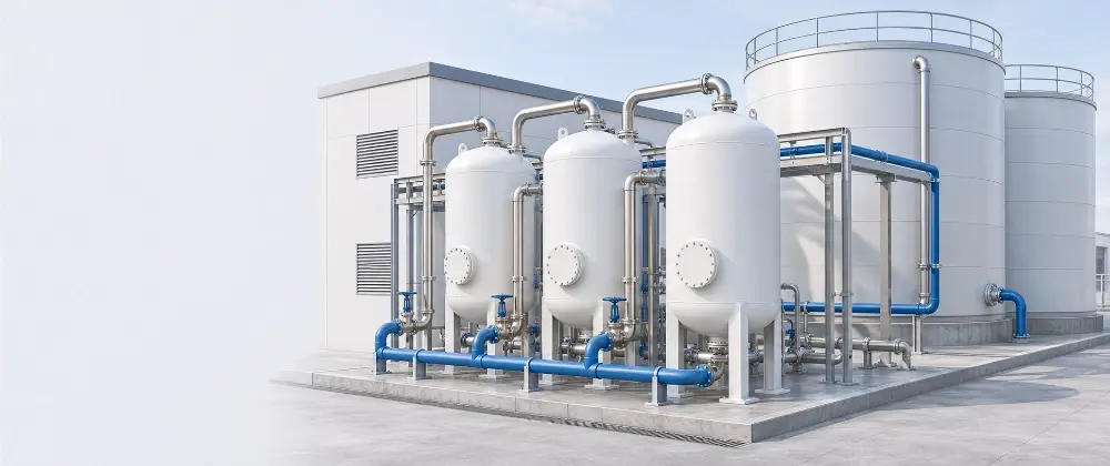
Atmospheric storage tanks handle equalization, backwash, treated water, and concentrate in PFAS treatment trains. This guide covers where each tank sits, how GAC and AIX design drives sizing, how to select material by role, and what belongs in the specification.
Storage Tanks in PFAS Treatment Trains
PFAS water treatment trains are defined by their media vessels and membranes, but atmospheric storage tanks carry the flow between them. Equalization, backwash, treated water, and concentrate tanks each see different flows, chemistry, and PFAS loading, and each is specified differently. With initial monitoring due April 26, 2027, and EPA citing steel volatility and media supply delays, those tanks belong on the project schedule early. This guide covers where storage tanks sit in the treatment train, how the treatment technology drives their sizing, how to choose material for each role, and what to put in the tank specification.
Where PFAS Drinking Water Rules Stand
EPA finalized the PFAS National Primary Drinking Water Regulation on April 26, 2024. It set maximum contaminant levels (MCLs) of 4.0 ppt each for PFOA and PFOS, with a maximum contaminant level goal of zero. Public water systems must complete initial monitoring by April 26, 2027, and meet the MCLs by April 26, 2029.
In May 2026, EPA proposed a federal exemption that would let eligible systems request until April 26, 2031, to meet the PFOA and PFOS limits, without changing the 4.0 ppt values. Systems that do not apply would keep the 2029 date. A separate proposal would rescind the MCLs for PFHxS, PFNA, HFPO-DA, and the Hazard Index mixture. EPA's rule page tracks the status of both.
EPA's case for the extension doubles as a procurement warning. The proposal cites inflation above 20 percent in construction materials for water system equipment from 2024 to 2025, volatility in steel markets, and supply chain delays on PFAS treatment media.
Drinking water is not the only driver. PFOA and PFOS are also designated CERCLA hazardous substances. Some publicly owned treatment works limit PFAS in the landfill leachate they accept. Facilities moving from AFFF to fluorine-free foam must capture and manage cleanout rinsate, and that wastewater volume often far exceeds the original foam concentrate volume.
Whichever deadline applies, storage tanks for equalization, treated water, and residuals belong in the compliance schedule. Specifying and procuring them early keeps tank delivery off the critical path to compliance.
On PFAS projects we start with the compliance date and work backward, so tank lead time fits inside the schedule.
How PFAS Is Removed From Water
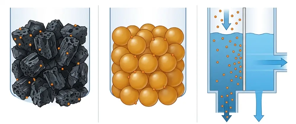
Conventional coagulation, filtration, and disinfection do not remove PFAS appreciably. Three PFAS treatment technologies are proven at full scale: granular activated carbon (GAC), single-use anion exchange (AIX) resin, and high-pressure membranes (reverse osmosis and nanofiltration).
- GAC: empty bed contact time (EBCT) of 7 to 20 minutes, with Massachusetts and Michigan applying 20 minutes as a minimum. Bed life runs 50,000 to 120,000 bed volumes, and adsorption capacity is lower for short-chain PFAS.
- AIX: EBCT of 2 to 3 minutes and bed life of 250,000 to 300,000 bed volumes, in a smaller footprint. Single-use resin is not backwashed.
- RO and NF: rejection of PFAS across chain lengths, with a concentrate stream that must be managed.
GAC and AIX contactors typically run in a lead-lag series configuration. The lead vessel does most of the removal, the lag vessel polishes and guards against breakthrough, and the vessels swap positions at change-out.
Contactor size follows from EBCT, which is bed volume divided by flow. At 1,000 gpm and a 10-minute EBCT, a GAC vessel train needs 10,000 gallons of bed volume, about 1,340 cubic feet of media. If influent flow rises above design, EBCT falls below its design value, which is why flow control upstream of the contactors matters.
Foam fractionation, which EPA names among emerging separation methods, uses no sorbent media. PFAS concentrates at the air-water interface of rising bubbles, and the foam is skimmed off as a concentrate. It is applied to landfill leachate, AFFF-impacted water, and RO concentrate.
The industry framing is separate, concentrate, destroy. Every separation step produces spent media or a liquid concentrate, and the liquid side of that equation has to be stored.
The treatment technology tells us which tanks a project needs, so it is the first question we ask after flow rate.
Where Tanks Sit in PFAS Water Treatment
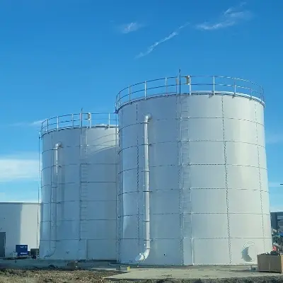
GAC and AIX contactors are typically ASME pressure vessels supplied with the treatment package, and large plants may use gravity contactors built as engineered basins. Atmospheric storage tanks are not contactors. They sit upstream, downstream, and alongside the treatment package, and they follow the same design logic as other wastewater storage tank applications. Most trains use some combination of five tank roles.
- Influent equalization: buffers flow and PFAS loading, holds EBCT at design, and settles solids ahead of the media.
- Backwash supply and recovery: used with GAC only, since single-use AIX resin is not backwashed.
- Treated water storage or batch hold-and-test: holds effluent until sampling confirms it meets the limit for discharge or distribution.
- Concentrate and residual storage: receives RO reject, foamate, and AFFF rinsate. This tank holds the highest PFAS concentration in the system and calls for secondary containment, the same practice used for chemical and hazardous liquid storage.
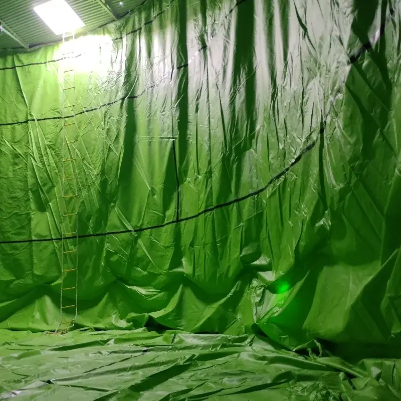
- Temporary storage for pilots: pillow tanks hold influent and treated water through pilot testing, before permanent tanks are specified. This temporary process water storage project shows the setup.
A landfill leachate foam fractionation pilot in Maine shows the layout at small scale. It used a raw influent tank, a treated effluent tank, and a separate high-concentration residuals tank, with secondary containment on all piping outside the containment area.
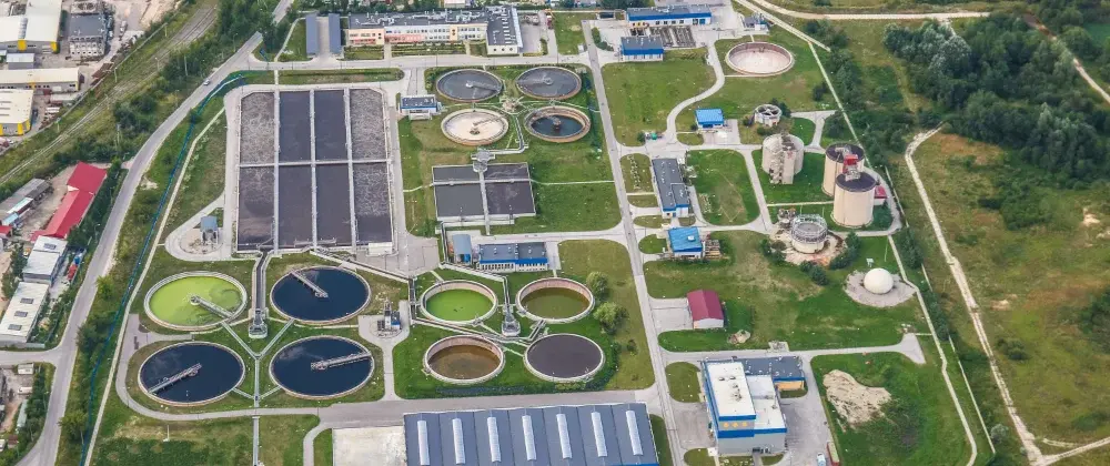
Each role sees different flow, chemistry, and PFAS concentration, so each tank is specified on its own terms.
Every tank role in the train has its own flow, chemistry, and containment requirements, so we quote each one on its own terms.
Choosing Tank Material for Each Role
PFAS at parts-per-trillion levels does not drive corrosion. Bulk chemistry does: pH, chlorides, total dissolved solids, temperature, suspended solids, oxidants, and treatment chemicals. Start material selection from the water analysis and screen candidates with the chemical compatibility tool.
Custom polypropylene and HDLPE tanks handle compatible service up to 200°F, in rectangular sizes up to 18,000 gallons and cylindrical sizes from 50 to 50,000 gallons. For potable water storage, the listing on the coating, tank liner, and wetted components governs the selection.
Wetted components need their own review. Fluoropolymers (PTFE, FEP, PFA, and FKM) fall within the PFAS class and are common in gaskets, O-rings, valve seats, and thread sealant. PFAS sampling protocols exclude PTFE and FEP from sampling equipment, and thread tape, gaskets, and seals are the first suspects when a sampling line returns PFAS. Intact fluoropolymers are classified within the sealing industry as polymers of low concern, but many engineers now specify fluoropolymer-free wetted components near sample points or require written material statements. Some components are certified PFAS-free by a 24-hour soak test, with the soak water non-detect under EPA Method 537 Modified.
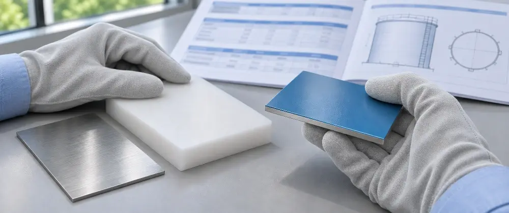
The water analysis is the first document we ask for, because pH, chlorides, and temperature narrow the material options before PFAS enters the conversation.
What to Include in the Tank Specification
A tank specification for PFAS service should let a supplier price and engineer each tank without guessing at its role. Cover these items for every tank in the train.
- Tank role and pressure rating: equalization, backwash, treated water, concentrate, or pilot, and confirmation that the tank is atmospheric rather than a pressure-rated contactor.
- Potable service: whether NSF/ANSI 61 applies to coatings, liners, and wetted components.
- Water chemistry: pH, chlorides, TDS, temperature range, suspended solids, oxidants, and treatment chemicals.
- Flow and residence time: design and peak flow, equalization or hold volume (checked against tank dimensions with the tank volume calculator), and the EBCT the tank protects downstream.
- Permanent or pilot service: design life, and whether pillow tanks will bridge the pilot phase.
- Wetted material restrictions: fluoropolymer limits near sample points, written material statements, and soak-test certification where required.
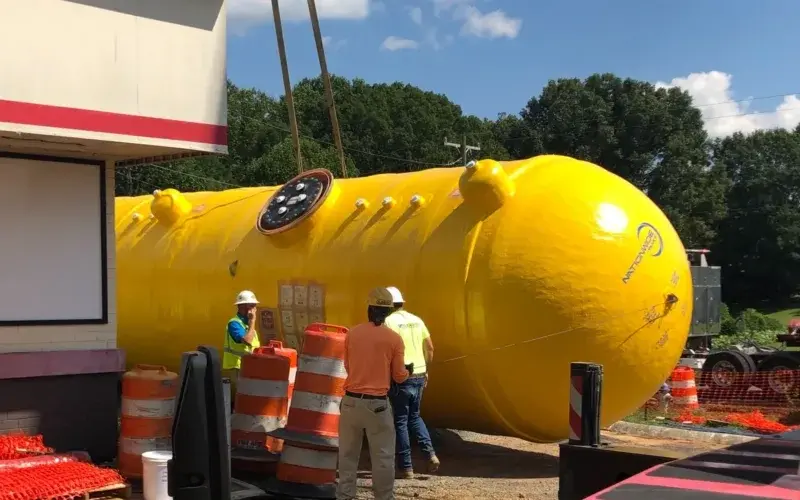
- Secondary containment: integral double wall, a bermed area, or containment for piping outside the containment area. This double-wall holding tank project shows one approach.
- Nozzles, levels, and instrumentation: connection sizes and locations, manways, vents, and fittings, level monitoring and overflow, and sample ports matched to the treatment package.
- Submittals: drawings, material and coating data, listings, and compatibility documentation. Engineering specs and compliance PDFs are available on request.
- Contacts: the engineer of record and the treatment integrator, so tank interfaces match the package.
One Clarion's Sales Specialists work from that information to match tank type and material to each position in the treatment train. Send the water analysis, flow basis, and tank roles through the PFAS project form to start the selection.
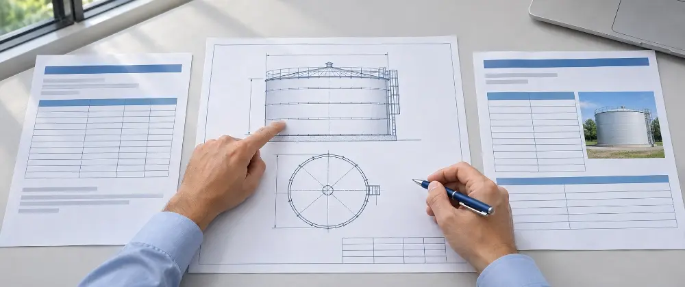
A specification that states each tank’s role, water chemistry, and containment requirement lets us quote it accurately the first time.